Home
› Logic Diagram Symbols - Execution logic block diagram of UDF program (the symbol T means time,... | Download Scientific ... : The following table lists many common symbols, together with their name, pronunciation, and the related field of mathematics.
Logic Diagram Symbols - Execution logic block diagram of UDF program (the symbol T means time,... | Download Scientific ... : The following table lists many common symbols, together with their name, pronunciation, and the related field of mathematics.
Logic Diagram Symbols - Execution logic block diagram of UDF program (the symbol T means time,... | Download Scientific ... : The following table lists many common symbols, together with their name, pronunciation, and the related field of mathematics.. Bit logic instructions run on the same principles as good old machine language, using nothing more than 0s and 1s to send signals. The following table lists many common symbols, together with their name, pronunciation, and the related field of mathematics. To set the value you may select the symbol and click its. In the solid state industry, they are used as the principal diagram for the design of solid state this article discusses the common symbols used on logic diagrams. Logic gates logic gate symbols logic diagram truth table.
A brief outline of the logic behind the symbols used within a data flow diagram. Ladder logic symbols are the fundamental programming components used in ladder diagrams. In the solid state industry, they are used as the principal diagram for the design of solid state this article discusses the common symbols used on logic diagrams. Bit logic instructions run on the same principles as good old machine language, using nothing more than 0s and 1s to send signals. From industrial text and video.
Ladder Logic Symbols - All PLC Diagram Symbols from www.plcacademy.com Relays in ladder logic tutorials. Logic diagrams have many uses. Electric and electronic circuit diagram symbols set of digital. Gate diagram symbols the logic diagram consists of gates and symbols that can directly replace an expression in boolean arithmetic. A bpmn diagram uses these symbols and elements to illustrate how the logic behind a workflow events: Ladder logic symbols are a set of symbols used in plc ladder diagrams. Electrical symbols electrical diagram symbols. To set the value you may select the symbol and click its.
From industrial text and video.
Logic diagrams are diagrams in the field of logic, used for representation and to carry out certain types of reasoning. Conceptdraw diagram is a powerful software for creating 2. Most logic gates take an input of two binary values, and output a single value of a 1 or 0. Complete vector set of electric and electronic circuit. A bpmn diagram uses these symbols and elements to illustrate how the logic behind a workflow events: Bit logic instructions run on the same principles as good old machine language, using nothing more than 0s and 1s to send signals. Learning the basic ladder logic symbols will give you a solid foundation. Learn vocabulary, terms and more with flashcards, games and other study tools. All circuit symbols are in standard format and they are mostly used to draw a circuit diagram and are standardized internationally by the ieee. Logic diagrams have many uses. Ladder logic symbols are the fundamental programming components used in ladder diagrams. A logic gate is a device that can perform one or all of the boolean. Electrical symbols electrical diagram symbols.
The leader in electrical, motor control and plcs video training programs. Conceptdraw diagram is a powerful software for creating 2. And data size will be defined in byte, word. A bpmn diagram uses these symbols and elements to illustrate how the logic behind a workflow events: To set the value you may select the symbol and click its.
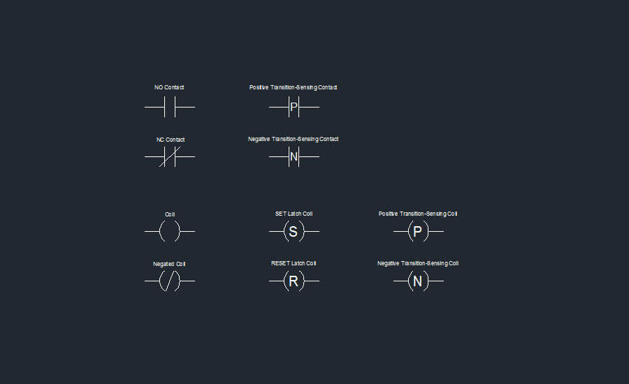
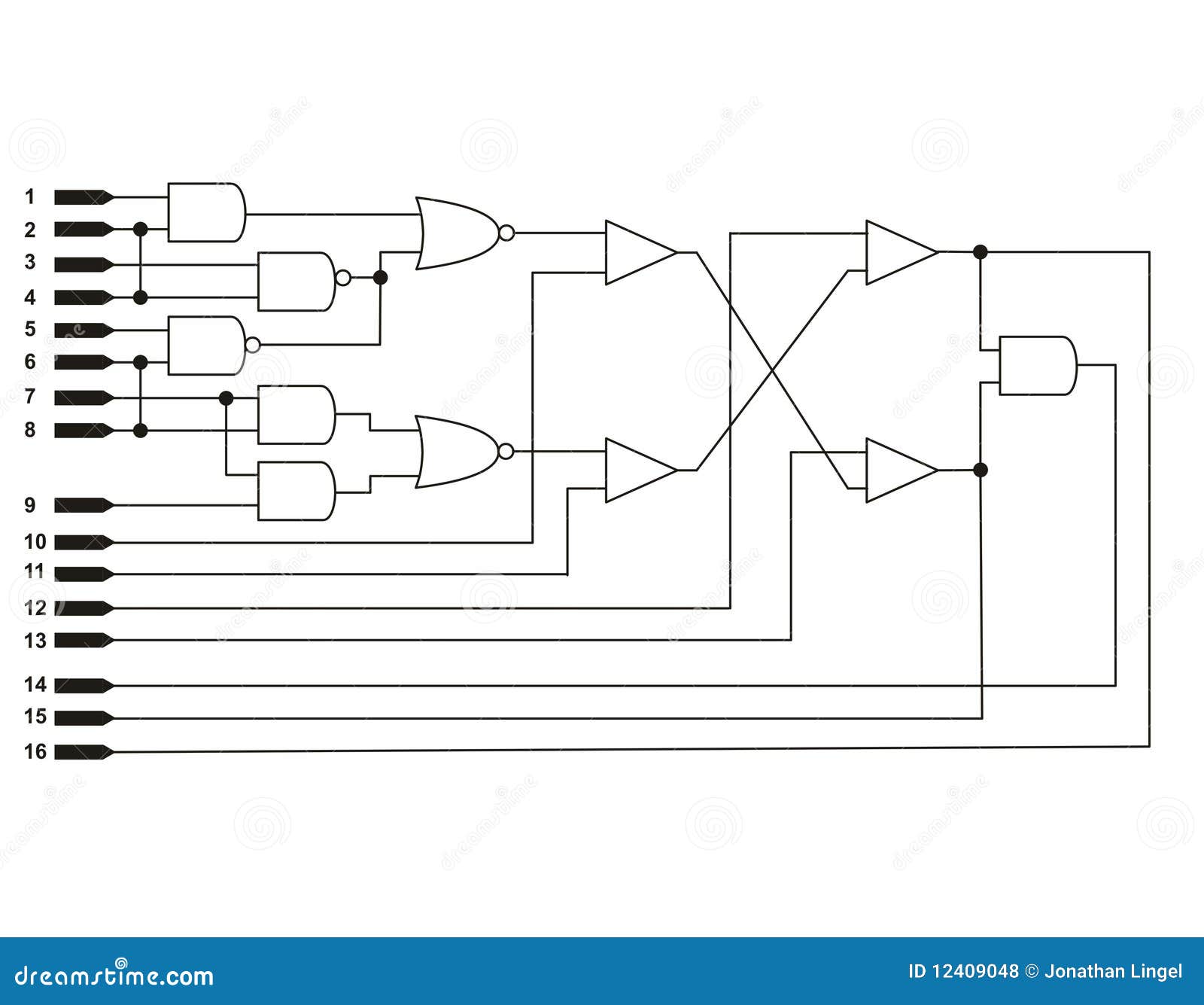
Logic diagram stock illustration. Illustration of symbols - 12409048 from thumbs.dreamstime.com In ladder logic symbolism, an electromechanical relay coil is shown as a circle, and the contact(s) actuated by the coil as two parallel lines, almost like a capacitor symbol. And data size will be defined in byte, word. Bit logic instructions run on the same principles as good old machine language, using nothing more than 0s and 1s to send signals. In logic, a set of symbols is commonly used to express logical representation. Logic gate template drafting and design templates stencil symbols. Engineering symbology, prints, & drawings logic diagrams. Logic diagrams have several applications in investigations, and are most often developed in an iterative fashion. In the solid state industry, they are used as the principal diagram for the design of solid state this article discusses the common symbols used on logic diagrams.
Events are circular symbols that serve as a trigger:
Complete circuit symbols of electronic components. Electric and electronic circuit diagram symbols set of digital. The leader in electrical, motor control and plcs video training programs. The symbol in a ladder logic diagram represents a. A logic gate is a device that can perform one or all of the boolean logic operations and. A brief outline of the logic behind the symbols used within a data flow diagram. Learn vocabulary, terms and more with flashcards, games and other study tools. From industrial text and video. Logic diagrams have many uses. All the ladder logic symbols or plc programming instruction available in the format of bit logic , arithmetic, logical, counters and timers etc. The logic diagram consists of gates and symbols that can directly replace an expression in boolean arithmetic. Logic diagrams have several applications in investigations, and are most often developed in an iterative fashion. Bit logic instructions run on the same principles as good old machine language, using nothing more than 0s and 1s to send signals.
Understanding substation single line diagrams and iec. Circuit symbols are used in circuit diagrams (schematics) to represent electronic components. The symbol in a ladder logic diagram represents a. As shown in the event tree logic diagram in figure 31.4, in the early stages of an. In logic, a set of symbols is commonly used to express logical representation.
Diagrammatic System from people.artcenter.edu There are ___ basic i/o symbols used in the programming diagrams for programmable. A bpmn diagram uses these symbols and elements to illustrate how the logic behind a workflow events: A logic gate is a device that can perform one or all of the boolean logic operations and. The symbol in a ladder logic diagram represents a. Understanding substation single line diagrams and iec. Logical not the output is a logic one if the input is a logic zero. Electrical symbols electrical diagram symbols. Relays in ladder logic tutorials.
The following table lists many common symbols, together with their name, pronunciation, and the related field of mathematics.
Logic gates process signals which represent true (1, high, +vs, on) or false (0. Logic gate template drafting and design templates stencil symbols. Figure 10 symbols for complex logic devices identify the symbols used to denote a logical 1 (or high) and a logical 0 (or low) as. Circuit diagrams can be created with thousands of possible shapes and from transistors to logic gates, you'll find icons that are modeled to international standards. In logic, a set of symbols is commonly used to express logical representation. Ladder logic symbols are a set of symbols used in plc ladder diagrams. The following table lists many common symbols, together with their name, pronunciation, and the related field of mathematics. Logic drawings are diagrams representing the logical elements and their interconnections. Logic symbols, truth tables, and equivalent ladder/plc logic diagrams. Building our logic symbols diagram starts with bit logic instructions. Power recovery logic diagram symbols. All circuit symbols are in standard format and they are mostly used to draw a circuit diagram and are standardized internationally by the ieee. Learn vocabulary, terms and more with flashcards, games and other study tools.