Home
› Shared Neutral Wiring Diagram : 31 Common Household Circuit Wirings You Can Use For Your Home 2 : And it is why a lot of people don't like them in residential.
Shared Neutral Wiring Diagram : 31 Common Household Circuit Wirings You Can Use For Your Home 2 : And it is why a lot of people don't like them in residential.
Shared Neutral Wiring Diagram : 31 Common Household Circuit Wirings You Can Use For Your Home 2 : And it is why a lot of people don't like them in residential.. The shared neutral wire is also called a common neutral wire, and this arrangement is known as an edison circuit. It reveals the parts of the circuit as streamlined forms, as well as the power and also signal links in between the devices. As there is no need of neutral wire in 240v single phase supply but some 240v single phase appliances are needed to be wired with the neutral wire as well such as hot tub spa and dryer etc. I want to move one of the lighting circuits to a generator transfer panel. Bond the ground wires, connect the neutral wires in the switch box and share the power source for the switches, then cable out to the light fixture boxes.
Always wire the neutral pigtail wire that is connected to the breaker directly to the panel's neutral bar. The wire on the right side of the open (goes to the load) is 120v to ground. It doesn't make any difference if it's in parallel or in cross. Here's a diagram to help you understand the situation, and why it happens. The voltage across the neutral is still zero, or very close.
How Does A Neutral Wire And A Common Wire Differ Quora from qph.fs.quoracdn.net The red and black are used for hot and the white neutral wire at the switch box allows for powering a timer, remote control, or other programmable switch. The actual wire connections are quite easy to understand. If that's true, now the 1st gfci from the left will sense a difference of 5a and should trip because no current is flowing through its ungrounded (red) wire, but 5a is flowing through its neutral. It's true that multiwire branch circuits reduce raceway size, voltage drop, and the number of conductors. Always wire the neutral pigtail wire that is connected to the breaker directly to the panel's neutral bar. For use with relay systems it is important the there is a single disconnect for each line, so a multipole breaker would be required to have a common neutral. And it is why a lot of people don't like them in residential. In the diagram above right, both phase a and b breakers or switches are open.
This arrangement is typically used in a kitchen where two separate appliance circuits are needed in close proximity to each other.
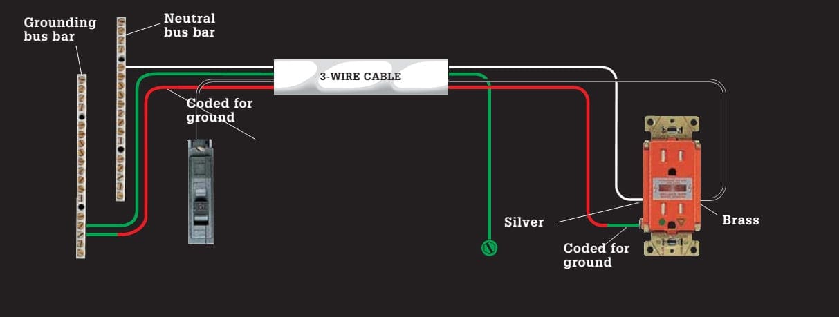
A wiring diagram is a streamlined conventional pictorial depiction of an electrical circuit. The actual wire connections are quite easy to understand. Wire the load hot and the load neutral directly to the arc fault. Here is a diagram of a standard switch with a neutral wire: It's true that multiwire branch circuits reduce raceway size, voltage drop, and the number of conductors. This photo is an example of a multiwire branch circuit preferred wiring diagram. I need a wiring diagram for my chevy 2500hd year 2008 with the duramax wiring diagrams spare parts catalogue fault codes free download. Kitchen split receptacle circuit wiring diagram: The red and black are used for hot and the white neutral wire at the switch box allows for powering a timer, remote control, or other programmable switch. It doesn't make any difference if it's in parallel or in cross. Although the current in a shared neutral may be almost zero when the loads are balanced, it is important to use copper cables that can carry currents during a load imbalance. As there is no need of neutral wire in 240v single phase supply but some 240v single phase appliances are needed to be wired with the neutral wire as well such as hot tub spa and dryer etc. The shared neutral will easily take the current and there will be very little voltage on it.
Collection of two pole gfci breaker wiring diagram. Simply moving one of these breakers to a different panel position could correct the problem but unless the two breakers are placed side by side and connected with a common trip tie the wiring would still be unsafe. Bond the ground wires, connect the neutral wires in the switch box and share the power source for the switches, then cable out to the light fixture boxes. The power can come from either the switch box or the fixture box and a set of electrical switch wiring diagrams will explain each of these scenarios to you clearly. Therefore, 5a is on all the neutral wire in the diagram, because they're all pigtailed together.
31 Common Household Circuit Wirings You Can Use For Your Home 2 from electrical-engineering-portal.com I don't know about canada, but the nec does allow this if the neutral is sized appropriately. Chevy silverado radio wiring diagram image. Because the two circuits are from opposite sides of the panel, the neutral will only carry the unbalance load. These feeder wires are known as the line wires. For use with relay systems it is important the there is a single disconnect for each line, so a multipole breaker would be required to have a common neutral. Article 100 defines a multiwire branch as two or more ungrounded circuit conductors with a common grounded (neutral) conductor. With the switch on, the power travels through the load (in this case, a light bulb filament), and back on the neutral, but no connection to the grounded buss bar, and that is how you get a shock from a neutral! The voltage across the neutral is still zero, or very close.
Where in the code does it say that sharing a neutral is acceptable?
Switch wiring diagrams a single switch provides switching from one location only. It doesn't make any difference if it's in parallel or in cross. Why are multiwire branch circuits used? Connect live (or a hot wire) to the common (or black) terminal of the first switch. These feeder wires are known as the line wires. This will cause some interaction between dimmers on the same neutral wire. The following wiring shows an electric stove, range or dryer has been wired and protected through a twp pole afci circuit breaker. Because the two circuits are from opposite sides of the panel, the neutral will only carry the unbalance load. Bond the ground wires, connect the neutral wires in the switch box and share the power source for the switches, then cable out to the light fixture boxes. Kitchen split receptacle circuit wiring diagram: The shared neutral wire is also called a common neutral wire, and this arrangement is known as an edison circuit. This diagram illustrates the arrangement for a 20 amp, 120 volt double receptacle circuit with a shared neutral wire. Where in the code does it say that sharing a neutral is acceptable?
In my mind, the main arguement against shared residential circuits are that they are advanced, and can be difficult when remodelling or doing maintainance. This diagram illustrates the arrangement for a 20 amp, 120 volt double receptacle circuit with a shared neutral wire. There must be a voltage potential between the ungrounded conductors and an equal voltage potential from each ungrounded conductor to the. Each breaker is on the opposite pole. This is a line diagram to simplify this further.
Do We Connect The Output Neutral Of An Inverter To The Main Neutral Line Quora from qph.fs.quoracdn.net Although the current in a shared neutral may be almost zero when the loads are balanced, it is important to use copper cables that can carry currents during a load imbalance. No current means no voltage across the switch's power supply which means full voltage on the disconnected neutral wire. The load neutral does not go to the neutral bar as with a standard thermal magnetic breaker installation. I need a wiring diagram for my chevy 2500hd year 2008 with the duramax wiring diagrams spare parts catalogue fault codes free download. The neutral wire on the left side of the open (comes from the panel) is 0v. I want to move one of the lighting circuits to a generator transfer panel. So if you are using a toaster plugged into the top half, and it is using 8a on circuit #1, and the coffee maker plugged into the bottom half using 6 amps, then the neutral will only be. All questions and answers are based on the 2005 nec.
Kitchen split receptacle circuit wiring diagram:
This diagram illustrates the arrangement for a 20 amp, 120 volt double receptacle circuit with a shared neutral wire. The actual wire connections are quite easy to understand. Multiwire branch circuits can offer fewer conductors, reduce the raceway size and reduce voltage drop. Each breaker is on the opposite pole. The savings from multiwire branch circuits can come at a high cost. Why are multiwire branch circuits used? If that's true, now the 1st gfci from the left will sense a difference of 5a and should trip because no current is flowing through its ungrounded (red) wire, but 5a is flowing through its neutral. So if you are using a toaster plugged into the top half, and it is using 8a on circuit #1, and the coffee maker plugged into the bottom half using 6 amps, then the neutral will only be. The red and black are used for hot and the white neutral wire at the switch box allows for powering a timer, remote control, or other programmable switch. As there is no need of neutral wire in 240v single phase supply but some 240v single phase appliances are needed to be wired with the neutral wire as well such as hot tub spa and dryer etc. Article 100 defines a multiwire branch as two or more ungrounded circuit conductors with a common grounded (neutral) conductor. The shared neutral will easily take the current and there will be very little voltage on it. If the neutral is lost, a 110v circuit using a shared neutral can become a 220v circuit.